


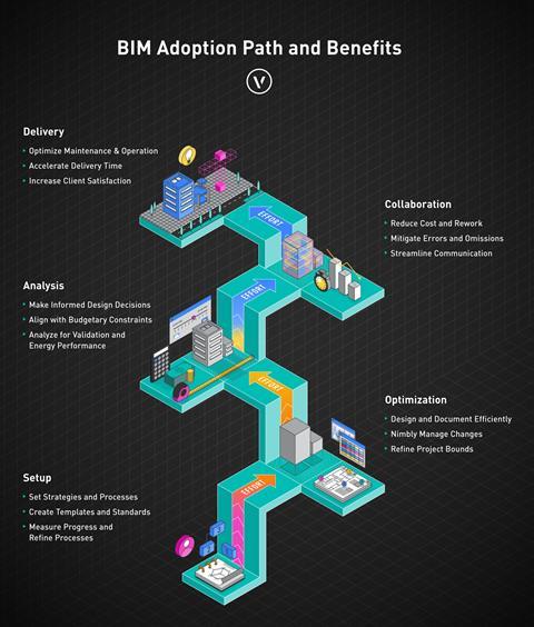
Sponsored by Vectorworks, this module explores how better project set-up, co-ordination and data management can help deliver BIM projects more reliably, efficiently – and successfully
Deadline for completion Friday 3 July 2026.

Building information modelling (BIM) is now a contractual expectation on many construction projects, yet its benefits are not always fully realised. The gap between firms that simply use BIM and those that get the most out of it by delivering a fully co-ordinated, data-rich information model remains considerable. This module covers the practical workflows, standards and tools that make the difference. It will cover:
- Project set-up
- Spatial co-ordination
- Data management
- Model interoperability
- Federation
- Issue management
- Asset data handover.
The examples are drawn from Vectorworks Architect, although the underlying principles apply across ISO 19650-compliant BIM workflows, regardless of authoring software.
Learning outcomes
- Recognise the key standards and documents that hold a co-ordinated BIM project together, including ISO 19650 and the BIM execution plan.
- Understand how a shared project origin point keeps all discipline models spatially aligned.
- See how classification systems and structured data turn a BIM model into a reliable source of information that can be checked automatically.
- Learn how federated models and the BIM collaboration format (BCF) are used to identify and resolve co-ordination issues.
- Understand how project information is managed during design (in a common data environment) and handed over to building owners as structured asset data (COBie) at completion.
1. The BIM process and information management framework
At its core, BIM is about ensuring the right information is available to the right people at the right time.
BIM is a way of creating and managing digital information about a building throughout its design, construction and use. Compared with traditional drawing-based workflows, it can improve efficiency, reduce errors and waste, and make project information more transparent.
In practice, BIM follows a cycle that repeats through every stage of a project:
- Agree on what information is needed, when, and by whom – typically captured in the employer’s information requirements (EIR) and BIM execution plan (BEP)
- Produce co-ordinated models containing both geometry and structured data
- Federate, check and validate the information against the agreed requirements
- Share it with the wider team through a common data environment (CDE)
- Hand over structured asset data to the building owner at project completion.
At each project stage the cycle repeats, with information growing in detail and accuracy as the design develops.
The key difference from traditional practice is that modelled elements are not just drawings – they carry structured data. BIM requires teams to agree in advance what information is needed and how it should be organised, so everyone is working to the same standard.
This approach underpins what is often referred to as the “golden thread” of information: a clear, consistent record of a building’s design and construction. Under the UK Building Safety Act 2022, higher-risk buildings (HRBs) – broadly those at least 18m tall or seven storeys with two or more dwellings – must maintain a structured digital record of safety-critical information throughout their lifecycle. For BIM teams working on HRBs, this makes structured information management a regulatory requirement rather than just good practice: classification, property sets, version control and auditable change tracking all become evidence of compliance.
ISO 19650 and the information management framework
The international standard ISO 19650 – developed from the foundations of the earlier UK PAS 1192 suite – provides the framework for managing information over the whole life of a built asset using BIM. It defines roles, processes and terminology that create a common language across projects and organisations. Central to ISO 19650 is the concept of information requirements: the employer or client publishes its employer’s information requirements (EIR), which defines what information is needed, when, in what format and to what level of detail.
The design team responds with a BIM execution plan (BEP) – the project-specific plan for how information will be produced, managed and delivered. In simple terms, it is the project’s information brief: a single document that sets out which software will be used, how models will be co-ordinated, what data is required, and who is responsible for delivering it.
The BEP is a living document, updated as the project progresses from appointment through to construction. Practices that treat it as a one-off requirement at the appointment stage – producing a document and filing it away – tend to face the consequences later: models that cannot be federated because no one agreed on a common origin, data that fails validation because classification requirements were never defined, or files that arrive in the wrong format because exchange protocols were never established. Those who use the BEP actively, returning to it at each work stage and holding all parties to its commitments, generally find it pays back the effort many times over.
ISO 19650 also defines project roles:
- The appointing party is the client commissioning the work.
- The lead appointed party, typically the principal designer, is responsible for managing the information delivered by the supply chain.
- Appointed parties are the consultants and contractors producing that information, organised into task teams for specific deliverables.
Clear role allocation is what allows the EIR and BEP framework to function in practice.
The “level of information need” (LOIN) sets out how detailed a model element should be at each stage of the project, both in its 3D form and in the data attached to it. The aim is to ensure each model is detailed enough for what the team needs at the time, without teams either over-modelling early on or leaving out information that is needed later. LOIN is the ISO 19650 replacement for the older “level of detail” framework.
OpenBIM and interoperability
OpenBIM is an approach to collaborative working based on open, non-proprietary standards that is championed by buildingSMART International, the global non-profit organisation responsible for developing and maintaining the open standards that underpin BIM, such as IFC, BIM collaboration format (BCF) and information delivery specification (IDS). The principle is that project information should be shareable in a reliable, software-agnostic way, allowing teams to exchange data without loss or corruption.
A typical co-ordinated BIM project may involve an architect working in one platform, a structural engineer in another and an MEP engineer in a third. OpenBIM workflows, centred on the IFC file format and supported by standards such as BCF and IDS, provide the connective tissue that holds the collaborative process together.
The BIM collaboration format (BCF) is an open standard for communicating model-based issues during co-ordination, allowing precise viewpoints and tracked status to be shared between different software platforms. BCF is covered in more detail below.
The information delivery specification (IDS) is a relatively recent buildingSMART standard that lets clients define their information requirements in a machine-readable file rather than a written document. This enables BIM software to check models automatically against the requirements, rather than waiting for a co-ordinator to audit at a gateway review. IDS is also explained in more detail below.
2. Spatial co-ordination – getting project origins right
Of all the technical prerequisites for successful BIM collaboration, establishing a correct common project origin point is the most critical and the most frequently mishandled. A common project origin is a known, agreed real-world co-ordinate – defined in the BEP – that serves as the single spatial reference from which every discipline exports its model. When all discipline models share the same origin, they can be assembled into a federated model without offset errors, rotational discrepancies or the spatial misalignments that are a persistent source of frustration and rework on BIM projects.
The BEP must establish the agreed x, y and z co-ordinates of the project origin, typically expressed in the UK as Ordnance Survey National Grid eastings and northings (or as a localised co-ordinate value referenced to a site datum). It should also specify the rotation to true north. Every consultant appointed to the project should acknowledge these values in their own BIM execution documentation, and every model issued for co-ordination must be exported relative to them.
Origins in BIM authoring software
BIM authoring software typically manages several distinct reference points, and understanding their relationships is a fundamental co-ordination skill. In Vectorworks Architect, for example, three points govern spatial position:
- The internal origin is the software’s fixed mathematical anchor: the point from which Vectorworks calculates the position of every object in the file. It never moves and, by default, has no real-world co-ordinates – it simply sits at 0, 0. Think of it as a pin stuck in a piece of graph paper. The pin doesn’t move, but you can decide which patch of the real world the graph paper represents. The user origin and survey point are the tools you use to do that – to tell Vectorworks where in the real world the fixed pin actually sits.
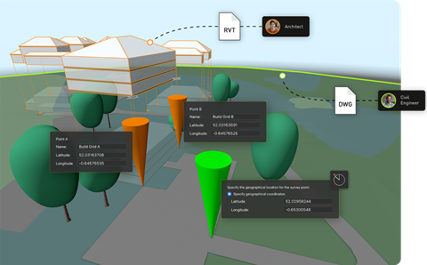
- The user origin is how you give the internal origin a real-world address. By shifting it from its default position, you are telling the software: “the point you export everything from is located at, say, national grid reference E530450, N182300.” From that point on, every object in the model carries real-world co-ordinates. So, when your model is combined with those from the structural engineer, MEP consultant and other disciplines, they all share the same reference point and fit together correctly.
- The survey point offers a more intuitive route to the same result. Rather than working backwards through the user origin offset, you type in the national grid reference agreed in the BEP, place the survey point at the internal origin, and Vectorworks aligns the co-ordinate grid automatically – including the rotation to match national grid orientation.
Georeferencing goes a step further than setting a project origin. Where the origin tells the software where the building is, georeferencing tells it what kind of co-ordinate system that location belongs to – British National Grid, a GPS-based latitude/longitude system, or one of many other national co-ordinate systems. This matters because co-ordinate systems are not all the same: they use different projections, different units and different reference points, so a pair of co-ordinates expressed in one system means something different in another.
True north and project north
Practitioners should also understand the distinction between true north and project north. True north means the model is oriented to its real-world compass bearing – as it would appear on an Ordnance Survey map. Project north means the model is rotated for drawing convenience, typically so that the building’s primary axes are horizontal and vertical on the sheet. A separate value records the angle between project north and true north, enabling IFC exports to be correctly oriented. Both conventions are valid; what matters is that all team members work to the same convention and that IFC exports correctly encode the rotation to true north, enabling other software applications to position the model accurately.
A good habit to get into on every BIM project is checking origin co-ordinates before issuing any model. This means verifying that the internal origin has the X and Y values specified in the BEP, and that the IFC export configuration includes the correct custom origin and rotation. Errors detected at this stage take minutes to correct; errors discovered later can cost days of rework.
3. Data management, classification and compliance
BIM models are only as useful as the data they contain. A geometrically accurate model that carries no structured data is little more than a sophisticated 3D drawing. The ability to interrogate the model, extract quantities, validate compliance, drive specifications and inform asset management from a single authoritative source is the core of BIM’s value proposition – and it depends on disciplined data management from the outset.
BIM models are also increasingly used as the data source for embodied carbon and other sustainability assessments. Tools such as One Click LCA, IES and Hawkins\Brown’s H\B:ERT can read material quantities and product data directly from a BIM model, turning carbon calculation into a by-product of the design process rather than a separate exercise. The accuracy depends on the same data discipline described above: properly classified objects, correctly populated property sets and consistent units.
BIM is often described in terms of dimensions beyond 3D geometry. 4D BIM links the model to programme data, enabling sequencing and construction simulation, while 5D BIM connects model elements to cost data for estimating and cost control. What is known as “lean BIM” meanwhile complements this by focusing on delivering only the information that adds value at each stage, reducing waste in both data production and co-ordination workflows.
Centralised data management
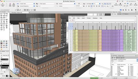
Every object in a BIM model – such as a wall, door, window, beam or fitting – can carry structured data: classification codes, fire ratings, acoustic values, specification references and manufacturer details. The challenge is ensuring that data is present, correct and consistently applied across thousands of objects and multiple design iterations. In Vectorworks Architect, the data manager is the tool that makes this manageable. It is a central configuration interface where you define which data fields – known as property sets – are attached to which object types, and what those fields should contain.
In practice, this means that as soon as an architect places a wall or door in the model, it automatically carries the data fields the project requires, without anyone having to populate them manually for each object. Validation rules within the data manager also flag any field that is empty or incorrectly populated as modelling proceeds, so errors are caught as they occur rather than being discovered in a wholesale audit before an issue date.
This shift – from checking compliance at the end to catching errors as you go – is one of the most significant advantages of a well-configured BIM workflow. It also means the model should be genuinely data-ready when the issue date arrives, rather than requiring a last-minute cleaning exercise.
Classification systems
Classifications are a standardised coding system that gives every type of building element a unique, universally recognised identifier. Every building contains hundreds of different elements – walls, doors, roof lights, fire dampers, drainage pipes and so on. On a project involving architects, engineers, contractors, cost consultants and facilities managers, all working in different software, you need a shared language for referring to each element consistently. Without one, an architect’s “rooflight”, a contractor’s “skylight” and a cost consultant’s “glazed roof opening” may all refer to the same thing – or not.
Classification systems solve this by assigning each element type a code from an agreed national or international list. In the UK that list is Uniclass 2015. That code then travels with the object through the BIM model, into the specification, into the cost plan, and eventually into the asset management system – so the same piece of information flows through the entire project lifecycle without getting lost in translation. In North America, OmniClass and MasterFormat are widely used, while other markets maintain their own national systems. Regardless of which system applies to a given project, the principle is the same: objects in the model should carry a recognised classification code that enables them to be unambiguously identified, counted, specified and managed.
So Uniclass 2015 provides a consistent way to classify building elements and systems, while ISO 19650 defines how information about those elements is produced, managed and exchanged across the project.
Assigning classification codes manually to every object in a large model is both time-consuming and error-prone. Modern BIM authoring tools support automated classification assignment based on object type or IFC entity – all door objects receiving the appropriate Uniclass code, for instance, with manual overrides available where the default assignment does not apply.
Automated classification feeds directly into specification workflows: tools such as NBS Chorus can scan the BIM model to identify all wall types, door styles, window configurations and material assemblies, presenting the specifier with a complete inventory of elements that require specification clauses. The result is a tighter, more auditable link between the model and the specification – and one in which changes to either are reflected in the other.
Information delivery specification and automated validation
Once classification and property set requirements are agreed, the next challenge is enforcing them consistently – across a project involving multiple people, multiple design iterations and potentially dozens of object types. The information delivery specification (IDS) is a buildingSMART standard designed to address exactly this. Rather than relying on a written document that everyone must read and interpret individually, IDS expresses the client’s information requirements in a machine-readable file that sets out precisely which object types must be present, what classifications they must carry, which property sets must be populated and what values are acceptable.
IDS files act as a digital checklist for BIM models, allowing teams to automatically check whether required information has been included. When integrated into design workflows, they can flag missing or incorrect data as the model develops, helping teams resolve issues early rather than at formal review stages.
Non-compliances can be sent directly to a BCF issue list for tracking and resolution (see section 5 below). This closed loop – from requirement definition through automated validation to structured issue management – is a significant improvement in how information compliance is managed on BIM projects, reducing both the volume of issues at key milestones and the cost of resolving them.
4. IFC, model interoperability and file exchange
IFC is the standard file format used to exchange BIM models and their data between different software platforms without loss of information.
An IFC model can be viewed, measured, federated, clash-detected, cost-estimated and validated by any IFC-compatible application – irrespective of which tool created it. Importantly, IFC is not intended to be edited directly: its read-only nature preserves the integrity of each discipline’s model while enabling comprehensive co-ordination across the project team.
IFC is structured around entities – top-level object types such as IfcDoor, IfcSlab and IfcWall – each of which carries standard property sets containing structured data fields. IfcDoor, for example, includes the property set Pset_DoorCommon, which contains fields for fire rating, acoustic performance and accessibility compliance. Correct population of these property sets is what makes an IFC model useful for downstream processes; an IFC with accurate geometry but empty property sets offers limited value beyond visual co-ordination. This is why data management configuration – ensuring that property sets are automatically populated as objects are created – is worth investing in at the start of the project.
Configuring and checking IFC exports
Setting up IFC export correctly requires attention to several factors:
- Ensuring all objects have the appropriate IFC entity assigned (built-in plug-in objects typically handled automatically, custom geometry requiring manual assignment)
- Confirming that required property sets are populated through data manager mappings
- Mapping document layers to building stories
- Configuring the export origin and true north rotation to match the agreed project co-ordinates from the BEP.
It is good discipline to open every IFC export in a viewer before issuing it to the team, confirming that geometry is complete, data is present and the model is correctly positioned. This simple quality-control step will catch most co-ordination problems before they reach other members of the design team.
Working with Revit files and cloud processing
Many architectural practices work alongside engineers, contractors and clients who use Autodesk Revit. Where IFC exchange is the preferred OpenBIM route, some workflows require direct Revit file exchange – for instance where a client explicitly requires a Revit deliverable, or where a structural engineer’s Revit model is being referenced for co-ordination. BIM authoring tools that support both import and reference of Revit files – with granular control over which object types are included and how they map to native objects – give the flexibility to work confidently in mixed-software environments without duplicating effort.
Cloud-based file conversion addresses one of the challenges to maintaining multiple output formats: the processing overhead of generating Revit exports from a non-Revit authoring environment. When conversion is handled in the cloud rather than on the design workstation, the designer can continue working while exports are processed, scheduled and delivered – including multiple Revit versions simultaneously, which is valuable when consultants and contractors are running different software releases.
5. Model federation, clash detection and BCF workflows

A federated BIM model brings together separate discipline models into a single co-ordination view, without merging them. Each team retains ownership of its own model.
The value of federation is that it allows co-ordination problems to be identified and resolved before work starts on site. Dimensional clashes, structural elements that penetrate services routes, ceiling heights that conflict with duct distributions, slab penetrations that have not been co-ordinated with structure – all become visible in the federated model in a way that is impossible to detect by reviewing discipline drawings separately.
Earlier clash detection means cheaper resolution: a clash identified during design development costs a fraction of what it would cost to resolve on site. The ability to federate models also enables improved cost planning and programme confidence, since more information is available up front and specification decisions can be confirmed earlier in the process.
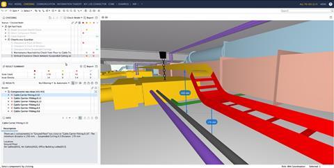
Designers can bring other consultants’ models into their authoring software for visual co-ordination, while each model remains separate and owned by its originating discipline. Specialist software can then validate the combined dataset more rigorously: Solibri, for example, can check geometry, clearance, accessibility compliance and Building Regulations requirements across the full federated model, going beyond the visual co-ordination that authoring-tool federation supports.
BCF workflows for issue management
BCF is an open standard for communicating model-based issues. Rather than a lengthy email chain or a PDF markup, a BCF issue contains a precise model viewpoint, a clear description of the problem, an assigned responsible party and a status that tracks resolution.
BCF files can be exchanged directly between applications or uploaded to a server-based issue management platform where the entire project team can view, update and track issues in real time.
Effective BCF workflows require consistent discipline: issues should be clearly described in actionable terms, correctly assigned to the responsible party, and marked as resolved only when the underlying problem has been addressed in the model. On complex projects with hundreds of active issues, the ability to filter by priority, discipline, assigned party or status keeps the process manageable.
The integration of IDS validation failures directly into the BCF issue list – creating a traceable link between data requirements and the issue management process – is a particularly efficient mechanism for quality control, ensuring that information deficiencies are tracked with the same rigour as geometric clashes.
6. The common data environment and COBie handover
A common data environment (CDE) is the agreed protocol and place where all project information is stored and shared. It ensures that everyone in the team is working from the same, up-to-date information. Rather than being a specific piece of software, it is a structured way of organising and controlling project files so that information is issued, checked and updated in a consistent way.
Within a CDE, information moves through defined states as work progresses. ISO 19650 uses four:
- Work in progress (still being developed by the team that owns it)
- Shared (issued for co-ordination but not formally approved)
- Published (approved for use by the wider team)
- Archive (a record of past versions).
These states are usually controlled by file metadata or folder structure, and ensure that team members never accidentally use draft information as if it were authoritative.
ISO 19650-2 also specifies a structured naming convention for information containers, combining project, originator, volume, level, type, role and number into a single filename, so that files can be filtered, sorted and traced through the CDE without ambiguity.
A CDE can be set up using specialist construction platforms, cloud storage, or a mix of both. What matters is that there is a single, trusted location for project information, with a clear system showing whether information is still being worked on, shared for co-ordination, formally issued, or stored as a record. This allows everyone on the project to understand whether information is ready to use or still in development.
Cloud-based systems that link directly to BIM software allow project models and drawings to be updated and shared automatically. For example, model files can be exported to formats such as IFC or PDF overnight, so the latest information is ready for the team each morning without anyone having to do it manually. This reduces admin work and helps ensure that the shared project information is always up to date.
Document review tools allow clients, contractors and consultants to view, mark up and comment on drawings from any web-enabled device, with feedback fed directly back into the authoring software for resolution. This significantly shortens what would otherwise be a slow, email-based review process.
Project-sharing, where multiple team members can work at the same time within a single hosted model, also helps to resolve version control issues that are common in traditional folder-based workflows, particularly on larger projects.
COBie and asset data handover
Construction operations building information exchange (COBie) is a non-proprietary data standard for delivering asset information at project handover. While IFC is the vessel for geometric and property data during design and construction, COBie is the structured format through which the building owner or facilities manager receives the information they need to operate and maintain the asset: equipment schedules, warranty data, maintenance requirements, spare parts lists and supplier contact information.
The most important principle of COBie is that the data is accumulated progressively throughout design and construction – embedded in the BIM model as objects are created and specified – rather than compiled manually at the end of the project. The BEP should include a COBie responsibility matrix defining which elements require COBie data, who populates it and at which project stage. For the architectural team, this typically means ensuring that specified products and components – anything requiring maintenance, repair or replacement during the building’s operational life – carry the standard COBie property sets populated with manufacturer and installer data.
When COBie data is embedded within the IFC schema alongside other standard property sets, it is automatically included in IFC exports and can be validated in model-checking software such as Solibri. Pre-formatted COBie worksheets within BIM authoring tools can extract this data in the standard spreadsheet format required for handover, providing a dynamic view that updates as the model develops. This approach eliminates the time-consuming and error-prone process of manually compiling asset schedules from disparate sources at the end of the project – a process that has historically resulted in incomplete or inaccurate handover documentation.
Summing up
Delivering a co-ordinated BIM project requires clear processes as well as technical skill. Co-ordination starts with agreeing a common project origin so that all models align correctly. Data quality is then built into the workflow through consistent classification, structured property information and ongoing validation, rather than being checked only at the point of issue. Model federation and BCF-based issue tracking allow co-ordination to take place during design, reducing the need for costly changes on site.
Effective BIM is not defined by software capability but by disciplined information management: clear requirements, consistent data, co-ordinated models and verifiable outputs.
Please fill out the form below to complete the module and receive your certificate